Software Documentation
- Unity - basic setup
- Getting started with Unity and VR
- Setting the scene
- Basic Teleportation
- Customizing controls
- UI events
- Finishing touches
- 3DTiles
- Unity with optional VR controls
- Initializing non-VR player character
- Switching from VR to non-VR mode in the Editor
- Switching from VR to non-VR mode at runtime
- Unity - inverse kinematics for robot arms
- Inverse Kinematics Scripts
- Pick-and-place and IK Controller
- Customizing the IKController for Different Applications
- Unity and Arduino - MQTT connection
- Unity - API Interface
- Unity - MQTT interface
Unity - basic setup
Tutorial for setting up Unity for VR using the XR Interaction Toolkit.
Getting started with Unity and VR
Before you get started, make sure that your VR headset and controllers are properly connected to your workstation. For additional tips on how to get started with the HTC Vive headset, consult the [hardware guide].
In the SteamVR settings, make sure that the Current OpenXR Runtime is set to SteamVR instead of Oculus, especially if a VR headset other than the HTC Vive was used on your current computer.
Create a new Unity project using the latest official version. It is beneficial at this stage to check for an updated version, but the rest of this guide will assume you're working with version 2021.3.19f1. Select the Universal Render Pipeline as the project type. This format provides the highest graphics fidelity.
Create a new empty scene in your project. Go to Window>Package Manager, choose Packages:Unity Registry from the drop-down menu, then search for XR Interaction Toolkit and install the package. The version used in this guide is 2.2.0. From the samples in the XR Interaction Toolkit, import the Starter Assets. Install the XR Plugin Manager as well.
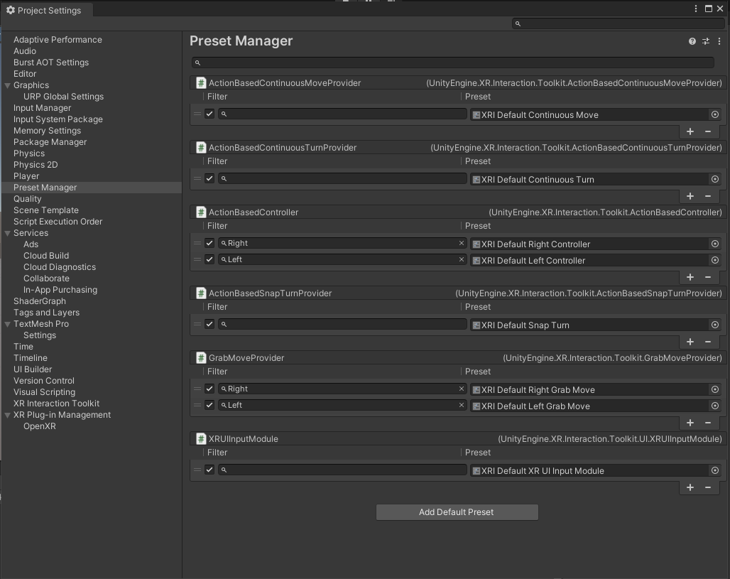
Navigate to Edit>Project Settings>Preset Manager.
In the Project file explorer, navigate to Assets > Samples > XR Interaction Toolkit > 2.2.0 > Starter Assets, open a preset in the inspector, then click Add to ScriptName Default. You should see the preset appear in the preset manager. Repeat this step for all the other presets available in the Starter Assets folder. Make sure that you label the presets for the Left and Right controllers using the filter. If everything is set up correctly, this is what you should see in the Preset Manager:
You' re now ready to start building your VR scene in Unity!
Setting the scene
Now that all the project settings have been updated to work with our VR setup, it's time to build our VR scene.
First, create a plane game object at coordinates 0,0,0 to serve as the floor. Then, create an XR Origin (VR) object. This object contains a camera offset, which defines the height of the camera corresponding to the headset in space, the main camera object, and the two controllers. If you run the game now, you' ll notice that your head movements are tracked, but you cannot see the controllers. That's because we haven' t assigned them an asset yet!
To fix that, you can import the vr_controller_vive_1_5 asset from the VR Starter Template, simply by dragging and dropping the asset from the asset folder to the controller objects. Rotate the assets (not the parent controllers!) by 180 degrees around the Y-axis to make sure that they' re matching their real-world orientation. To make the controllers appear more realistic, we can create a new material and set the Base Map to black or dark gray. Then, we drag this new material onto the lowest-level controller objects, which should be called whole_model_group1.
For each controller, you will also need to add the input handling preset. To do so, click on the slider icon in the top-right corner of the XR Controller (Action-based) dropdown, and select the XRI Default Left/Right Controller preset, depending on which controller you've selected.
Each controller should have an XR ray interactor, which allows us to use the controller buttons to interact with game objects and UI components. To test this, add a Sphere or Cube game object to the scene, and assign it a Rigidbody and an XR Grab Interactable component. When running the game, you should be able to grab the object by using the controller's trigger.
Basic Teleportation
Teleportation allows you to instantly move from a location to another in your VR environment. To get a teleportation system up and running, you first need to add a Locomotion System and a Teleportation Provider to your XR Origin object. Make sure that the XR Origin is assigned to the Locomotion System, and that the Locomotion System is assigned to the Teleportation Provider
From the Unity main menu, click GameObject > XR > Teleportation Area or GameObject > XR > Teleportation Anchor to create a plane on which teleportation is possible. On a Teleportation Area, you teleport to your pointed target on the plane's child collider, whereas a Teleportation Anchor specifies a pre-determined position and/or rotation in addition to the Teleportation Area. You can also add a Teleportation Area component to the Plane object we've previously set up as our floor.
You should now have a basic scene with the ability to teleport using your controllers. By default, teleportation is activated by the grip buttons on the HTC Vive controllers. The default ray interactors will turn from red to white if you're pointing at an area where you can teleport.
Customizing controls
In order to make your game or simulation more intuitive or accessible, you can modify the controller bindings inside your Unity project. Here, we will show how to change the teleportation controls from the default grip buttons to the trigger.
From the Assets folder, click on Samples > Interaction Toolkit > 2.2.0 > Starter Assets, then open the XRI Default Input Actions Import Settings. Select the XRI LeftHand Interaction menu, in the drop-down properties of Select you should see gripPressed [LeftHand XR Controller]. Change that path to triggerPressed [LeftHand XR Controller]. Repeat this step for Select Value, changing the path from grip [LeftHand XR Controller] to trigger [LeftHand XR Controller].
To avoid having two actions mapped to the same button input, you can also change Activate to gripPressed, and Activate Value to grip.
Go back to your LeftHand Controller in your scene, and under the XR Ray Interactor properties, check the box "allow Hovered activate". This way, you won't have to grip the controller to activate objects you're pointing at.
For the right controller, you can keep the default input actions. To make the right controller only interact with UI elements, the XR Ray Interactor can be modified. Change the Raycast Mask from Everything/Default to UI, and the right ray will only be able to interact with UI elements. This can be useful if you want to avoid accidental teleportation when pressing a UI button, for example.
UI events
To interact with Unity's built-in UI elements, you need to perform extra steps, particularly if you're dealing with 3D-tracked devices. The XR Interaction Toolkit package provides a number of new components that you can use to convert an XR controller to work seamlessly with the UI, as well as helper menu options that handle basic configuration settings.
Before adding a button, a slider, or any other UI element, click on GameObject > UI > Canvas to generate a Canvas which will contain all UI elements, as well as an EventSystem component. In the Canvas properties, change the Render Mode to World Space, and set the Event Camera to the Main Camera. Then, use the Scale property to make the Canvas fit your scene.
Important: If you directly modify the Width and Height of your Canvas instead of scaling it, the Canvas might not work as intended. This also applies to Buttons and other UI elements.
The Event System component acts as a central dispatch for UI events to process input, and update individual active canvases. Additionally, each Event System needs an Input Module to process input. The EventSystem component might have a Standalone Input Module or an Input System UI Module, which will prevent proper input processing. Remove the component, and add an XR UI Input Module to the event system.
Finally, add a Tracked Device Graphic Raycaster component to the Canvas, and set the Raycast Trigger Interaction to "Collide". This will allow your Raycast to actually hit elements on the Canvas instead of passing through them.
To test your setup, add a Button object as a child of the Canvas. If you select the button by pressing the trigger on your Right controller, the button should change color. Now, you can add your own script to the Button object, and change the On Click () property to run that script when the button is pressed.
Finishing touches
Now that all the basic elements are in place, you can add some features to the scene to make it more user-friendly.
First of all, change the color of the left and right controller object to easily tell them apart. To do this, click on the whole_model_group1 object, then on Material > Surface Inputs. Change the Base Map to a different color for each controller. In the Demo Project, you can see that the left controller is blue, and the right controller is red.
Now you can improve the looks of teleportation and raycasting. In the XR Ray Interactor properties, under Raycast Configuration, change the Line Type to Projectile Curve. You can also change the ray color: in the template, the Invalid Color Gradient is set to transparent. This makes the ray invisible, until it is pointed at a valid target.
A teleportation reticle can also be added to the ray. To prototype this, create a new cylinder, rename it Teleport Reticle, remove the collider, scale it down to 0.5 and lower the Y axis to create a disk shape. Create a new material called Reticle Base, set the shader to URP/unlit, set the surface type to transparent, choose a color, and decrease the alpha value to about 70. Drag the new material onto the Teleport Reticle object and assign the Reticle to the Reticle property of the Line Visual component. You can see a transparent reticle at the end of our ray which appears when hovering over an eligible object and provides some additional feedback to the player on their teleport location.
To make this element more interesting, you can use a ShaderGraph instead of a solid color. Right click in the Project folder and select Create > Shader Graph > URP > Unlit Shader Graph, then open the new shader in the shader editor. In the Graph Inspector, change the Surface Type to Transparent and the Render Face to Both. Now let's create two colors in the left-hand panel for the shader effect. Switch the Graph Inspector to the Node Settings window to view the properties for each color. Make the TopColor fully transparent, and the BottomColor your preferred shade. To create a gradient based on the height of the model, right click in the open space and select Create Node then search for Position. Update the Space value to Object. Create another node for Split. Connect the nodes by dragging the node marker from the output of Space to the input of Split. Create a Lerp node, then connect BottomColor to A, TopColor to B, and the output of Split to T. Next drag the Lerp Output to the “Base Color” Fragment. Create a new Split node and drag in the Lerp output, then drag the alpha channel from the split to the alpha on the Fragment. This will allow you to separately control the alpha values. The Shader setup is now complete. Click on Save Asset and return to the Scene. Right click on the Shader and select Create -> Material. This will create a new material with the shader already applied to it. Next apply the material to our teleportation reticle cylinder. Once applied, choose some colors and play around with the alpha channel.
3DTiles
Pointclouds
To convert pointclouds to 3dtiles format you can use this tool. It supports converting from las/laz, xyz, ply and wkb formats. This guide focuses primarily on the conversion from las/laz formats.
To install the tool execute the following commands to clone the project and install it with support for laz files. There are additional system dependencies that might have to be installed, which can be found here.
$ git clone https://gitlab.com/Oslandia/py3dtiles.git
$ cd py3dtiles
$ python -m venv .venv
$ source .venv/bin/activate
$ pip install -e .
$ pip install laspy[laszip]
To convert las/laz files to 3dtiles you can then use the following command with the python environment activated:
$ py3dtiles convert input1.laz input2.laz --out output_dir
You can optionally convert the CRS of the input to another one. Note that for the DTLab architecture a single unified CRS is needed for all files, so make sure to convert the input to EPSG:4326 if it is in another using the options --srs-in SRS_IN --srs_out 4326, specifying the input SRS of the las/laz files.
Reprojection, Compression & Merging
Reprojection
To reproject a 3d tileset to another CRS you can use the py3dtilers tool.
Compression
To compress a 3d tileset using draco you can use 3d-tiles-tools.
Merging
To merge multiple 3d tilesets together you can use 3d-tiles-tools.
Unity with optional VR controls
Initializing non-VR player character
In this tutorial, we will assume that your Unity project has already been set up for VR use with the XR Interaction Toolkit, as well as the Input System. To initialize a non-VR player character in an existing VR project in Unity, follow these steps:
- Create a new GameObject: In the Unity Editor, right-click in the Hierarchy panel and select "Create Empty." This will create a new empty GameObject. Name this object "Player".
- Attach the VR Mode Switcher script to the "Player" GameoObject. This script will allow you to enable/disable the VR Mode at runtime.
- Create a child GameObject: right-click on the Player GameObject in the Hierarchy panel and select "Create Empty". Name this object "Player Controller".
- Attach a Rigidbody: Select the "Player Controller" GameObject, then click on the "Add Component" button in the Inspector panel. Search for "Rigidbody" and add it to the GameObject. Set the "Interpolate" property to "None". The Rigidbody controller will handle physics for your player object.
Be careful with Mesh Colliders!
GameObjects that have a Rigidbody component only support Mesh Colliders that have Convex option enabled: the physics engine can only simulate convex mesh colliders.
- Attach a character controller: Select the "Player Controller" GameObject, then click on the "Add Component" button in the Inspector panel. Search for "Character Controller" and add it to the GameObject. The Character Controller component will handle the player's movement and collision.
- Add a 3D model or sprite: If you want a visual representation for your player character, you can add a 3D model or sprite. Import your desired model or sprite into Unity by dragging it into the Project panel. Then, drag and drop the model or sprite onto your Player GameObject in the Scene view or Hierarchy panel.
- Set up player controls: Attach a Player Input object and the Input System Test to the Player Controller. Open the "Events" drop-down menu, and add the corresponding function from Input System Test to each Event included in the Input Action Asset. Some example functions for things such as camera movement, player movement, and jumping are already included in the Input System Test script.
- Add a raycast for UI interaction: To enable the player character to interact with UI elements such as buttons or menus, you'll need to add a raycast. Attach the Raycaster script to the player character GameObject. This script uses the Physics.Raycast method to detect if the ray hits any UI elements and perform the desired actions accordingly, such as button clicks or menu selections.
- Test and refine: Save your script and go back to the Unity Editor. Disable the Xr Origin object to make sure that the game won't start in VR mode. Press the Play button to enter Play mode and test your player character initialization and movement. Make any necessary adjustments to the code or settings until you are satisfied with the result.
That's it! By following these steps, you can initialize a player character in Unity and have them ready for movement and interaction in your game.
Switching from VR to non-VR mode in the Editor
Here's how to change from a VR to a non-VR player view in the Unity editor:
-
Open your Unity project and make sure you have both the VR and non-VR player controllers set up. These controllers should be separate GameObjects, each with scripts and components attached to the player character.
-
In the Unity editor, locate the XR Origin. This GameObject is responsible for handling the input and movement in the VR environment.
-
Disable the XR Origin. You can do this by right-clicking on the script/component in the inspector and selecting "Disable" or "Remove". The XR Interaction Manager GameObject can remain active
-
Locate the non-VR player controller component. This component is responsible for handling the input and movement in the non-VR environment.
-
Enable the non-VR player controller component. If the component was already added but disabled, right-click on it in the inspector and select "Enable". If the component wasn't added yet, refer back to the previous tutorial on how to set up the non-VR player controller.
-
Save your changes by pressing Ctrl + S (Windows) or Command + S (Mac) or by navigating to File > Save Scene.
-
Enter Play mode by clicking the Play button at the top of the Unity editor or by pressing Ctrl + P (Windows) or Command + P (Mac).
-
You should now be able to see the non-VR player view in the Game view window instead of the VR view. You can use your regular input controls to interact with the game as a non-VR player.
That's it! You have successfully changed from a VR to a non-VR player view in the Unity editor. You can toggle between the two views by enabling/disabling the corresponding player controller scripts or components.
Switching from VR to non-VR mode at runtime
Enabling and disabling VR through keyboard input
-
Make sure you have both the XR Origin and non-VR player controllers set up in your Unity project. These controllers should be separate scripts or components attached to the player character.
-
Attach the "VRModeSwitcher" script to an empty GameObject in your scene.
-
In the Unity editor, drag and drop the XR Origin GameObject and the non-VR player controller GameObject into the appropriate fields of the "VRModeSwitcher" script component.
-
Save the script and return to the Unity editor.
-
Enter Play mode by clicking the Play button at the top of the Unity editor or by pressing Ctrl + P (Windows) or Command + P (Mac).
-
Press the (alphanumeric) 1 key to toggle between VR and non-VR modes at runtime. The corresponding player controller should be enabled or disabled based on the selected mode.
Enabling and disabling VR through an in-game button
Unity - inverse kinematics for robot arms
Inverse Kinematics Scripts
Purpose
This set of scripts provides inverse kinematics solutions tailored for the UR10 robot arm, complemented by a custom actuator. It's designed to facilitate the visualization of the robot grasping and positioning boxes conveyed by a belt system.
Prerequisites
Unity Setup:
Ensure your Unity project is initialized using the 3D URP (Universal Render Pipeline) template. This script was developed and tested for Unity Editor version 2021.3.19f1 and as such, stability of this script in future versions is not guaranteed.
The scripts can be downloaded, along with a demo project, can be downloaded from the DTLab GitLab page and then copied to the new Unity project. The essential scripts for Inverse Kinematics, without the pick-and-place functionality, are:
-
IKController-> to control the robot arm's movement -
DisableGravityForJoints-> to override the physics built into the URDF model -
MoveAlongPath-> to move the box along the conveyor belt
Required Packages:
For effective robot arm simulation and interaction, integrate the following packages:
- ROS TCP Connector
- Unity Robotics Visualizations
- URDF Importer
All the above packages can be sourced and installed from Unity Robotics Hub on GitHub. Alternatively, they can be imported from locally cloned repositories housing the packages.
Robot Arm Integration:
-
Using a URDF File: If your robot arm configuration is stored in a URDF file, navigate to the asset within Unity. Right-click and choose "Import Robot from Selected URDF file". This action will generate a 3D visual of the robot arm, incorporating the designated joints and their inherent physical constraints.
-
Without a URDF File: If you possess only a 3D render of the robot, devoid of joint articulation, consider importing this model into Blender. Within Blender, introduce "bones" to your model. These bones will enable the various robot segments to exhibit mobility and flexibility.
Setup and Installation
-
Script Integration: Begin by adding the IK script to your Unity project.
-
Setting up the IK Controller:
- Create a new empty GameObject within your scene.
- Rename this GameObject to IK Controller.
- Attach the IK Controller script to this GameObject.
-
Configuration:
- Assign the appropriate GameObjects to the Actuator and IK Target fields.
- For scenarios requiring multiple targets, ensure you populate the Target Array with the relevant GameObjects in the order they should be referenced.
-
Joints Array Setup:
- Populate the Joints array with all individual joints from the robot arm.
- Start with the base link (root of the arm) as Element 0 in the array.
- Conclude the array with the actuator as the final element.
By following these steps, you will have successfully set up the IK Controller to interact with your robot arm in Unity.
Pick-and-place and IK Controller
Overview:
The IKController class provides an inverse kinematics solution for robotic arms in Unity. It allows the robotic arm to adjust its joints to reach or point to a specific target position. This is achieved through the gradient descent algorithm.
Properties:
-
_targetGameObject: An array of GameObjects representing the targets the robotic arm should move towards.
-
actuator: The GameObject representing the end effector of the robotic arm.
-
ikTarget: The GameObject representing the inverse kinematics target.
-
endPoints: An array of Transforms that indicate the end points of the robotic arm.
-
_targetTransform: An array of Transforms associated with the
_targetGameObject. -
Joints: An array representing the joints of the robotic arm. The joints determine the rotation axis.
-
Angles: An array of floats representing the current angles of the robotic arm joints.
-
InverseKinematicController: A GameObject that serves as the controller for inverse kinematics.
-
suctionCupTransform: Transform component of the actuator.
-
delayedIKTarget: An instance of
DelayedIKTargetUpdateattached to the current GameObject. -
collisionPenalty: A penalty score added when joints come too close together to avoid self-collision.
-
target: The target Vector3 position that the robotic arm should move towards.
Constants:
-
SamplingDistance: The distance for sampling in the gradient descent algorithm.
-
LearningRate: The rate at which the angles are adjusted during the gradient descent.
-
DistanceThreshold: The threshold under which the arm is considered to have reached the target in terms of distance.
-
AngleThreshold: The threshold under which the arm is considered to have reached the target in terms of angle.
Methods:
Start()
Initializes the _targetTransform array by fetching the Transform component of each target GameObject. It also initializes the suctionCupTransform and sets the initial target for the robotic arm based on the Dropped flag.
StartMovementWithDelay()
Starts the inverse kinematics movement after a delay. Not used in the demo implementation, but can be used as an alternative to th distance-based default.
InverseKinematicCoroutine()
A coroutine that updates the target position to the position of the ikTarget and adjusts the angles of the joints to move towards this new target.
Update()
Called once per frame. Adjusts the target position based on various conditions and executes the inverse kinematics algorithm.
ForwardKinematics(float[] angles)
Given an array of joint angles, it computes the position of the end effector using forward kinematics.
DistanceFromTarget(Vector3 target, float[] angles)
Calculates the distance between the target position and the end effector's position.
AngleWithTarget(Vector3 target, float[] angles)
Calculates the angle between the target position and the end effector's position.
ErrorFunction(GameObject target, float[] angles)
Calculates the error between the end effector's position and rotation and the target's position and rotation.
PartialGradient(Vector3 target, float[] angles, int i)
Computes the partial gradient of the error with respect to a specific joint angle.
InverseKinematics(Vector3 target, float[] angles)
The core method for the inverse kinematics solution. Adjusts the joint angles so that the end effector moves closer to the target position.
Remarks:
The script adjusts the robotic arm's angles using the gradient descent algorithm to minimize the error function. The error function encapsulates the distance between the end effector and the target and potential penalties due to near-collisions between joints.
Ensure to have the required targets and joint GameObjects correctly set in the Unity Editor for this script to work as intended.
Customizing the IKController for Different Applications
The IKController script is a versatile framework for inverse kinematics (IK) and can be customized for various applications. Depending on your needs, you might want to adjust several properties or change the optimization function. Here’s how you can do so:
Serialized Fields for Editor Exposure:
Unity's Inspector is a powerful tool to tweak properties in real-time. By making variables into [SerializeField], even if they are private, you can expose them in the Unity Editor. This makes it easier to adjust values during runtime and tune your IK without having to modify the script directly.
For example, if you want to expose the LearningRate variable, simply modify its declaration:
[SerializeField] private const float LearningRate = 50f;
Now, LearningRate will appear in the Unity Inspector, allowing you to modify its value through the Unity Editor interface.
Tweaking Joint Properties:
Each joint (ArmJoint) is a critical component in the IK system. You might need to adjust the following properties for different robots or characters:
- Rotation Axis: Determines which axis (x, y, z) the joint will rotate around.
- Min/Max Angle: Constraints on how much the joint can rotate. This is essential to ensure that the joint doesn't rotate beyond its physical or desired limits.
- StartOffset: The starting position offset of the joint relative to its parent.
You can add these as serialized fields if you want to tweak them in the Unity Editor directly.
Enhancing the Error Function:
The current error function in the IKController script primarily focuses on the distance and angle to the target. However, in many real-world scenarios, other factors might be crucial.
Collision Handling:
Collisions between robot joints or between a robot and external objects can be problematic. You can enhance the error function to penalize configurations where joints overlap or come too close to other objects. To do this, integrate a collision checker that returns a high penalty value if a collision is detected.
For example:
if (JointCollisionDetected(i))
{
    penalty += HighCollisionPenaltyValue;
}
Energy Consumption or Efficiency:
For robots where energy efficiency is crucial, you might want to add a term that penalizes configurations requiring more energy. This could be based on joint angles, rotation speed, or other robot-specific parameters.
4. Changing Optimization Techniques:
The provided script uses gradient descent, which might not be optimal for all scenarios. Depending on your robot's complexity and the required precision, you might want to explore other optimization techniques or even machine learning-based approaches to find the best configuration.
Introducing New Constraints:
Depending on the robot's design, there might be specific postures or configurations that are undesirable or impossible. By adding custom constraints to the optimization process, you can ensure that the IK solution respects these constraints.
Remember, the IKController is a starting point. Depending on the complexity of your application, robot design, and requirements, you might need to expand and customize it further. Always test your changes in a controlled environment to ensure that the robot behaves as expected.
Unity and Arduino - MQTT connection
Description of how to connect Unity and an Arduino to an MQTT broker.
MQTT-Arduino-and-Unity
Table of Contents
Project description
This repository contains information on how to connect an Arduino to Unity via a MQTT broker. Both the Arduino and the Unity project are able to Subscribe and Publish to multiple MQTT topics. It is important to note that the provided code will need to be changed according to your project specifications. Additionally, the Unity project also has graph visualisation using Xcharts.
Unity overview
This section provides comprehensive information on using the MQTT client in Unity, along with instructions on how to display values on a graph within Unity. The MQTT client allows you to subscribe to MQTT topics, receive and publish messages, and integrate them into your Unity project.
The Unity project has 2 dependencies. These dependencies are already present within the project. When using the prefabs from this project these dependencies automatically get imported into your new project.
- MQTTnet 3.1.0 library; responsible for creating a MQTT client within Unity.
- Xcharts; responsible for the visualisation of the data with Unity.
As mentioned above, this repository also contains 2 prefabs that can be directly imported into your own Unity project. These prefabs can than be adjusted to your own needs.
- MQTT; contains the MQTTSubscriber and MQTTPublisher script. The MQTTSubscriber cannot be deleted from the prefab, as this contains the contains all relevant code that is needed for a connection with the MQTT broker. The MQTTPublisher script is only there for demonstation purposes (as will be shown below) and can be deleted from the prefab.
- ChartUpdater; This contains code that reads the data provided by the MQTT prefab and publishes it to the chart. This is not neccesary for a MQTT connection, but is used here for the demonstration.
Features
- MQTT subscription and publication within Unity.
- Debugging options to view messages in the Unity console.
- Support for MQTT brokers on specified TCP servers and ports.
- Optional use of credentials and encryption.
- Easy integration with Unity game objects and C# scripts.
Unity project walktrough
This Unity MQTT client allows you to easily connect to MQTT brokers, subscribe to topics, and publish messages. The MQTT publisher and subscriber can be attached to the same GameObject or separated into two GameObjects, offering flexibility and customization based on your project's requirements.
Getting Started
Configuring the MQTT subscriber
To set up the MQTT subscriber, follow these steps:
- Attach the MQTT subscriber script to a GameObject in your Unity project.
- Toggle the "Enable connection" option to establish a connection.
- Optionally, enable "Toggle Debugging" to print received and published messages to the Unity console.
- Configure the MQTT broker address (TCP server) and port according to your MQTT host settings.
- If necessary, provide credentials and enable encryption (e.g., for port 8883).
- Specify the "Topic Path" as the common path to access the topics you want to subscribe to.
- Populate the "Topics" list with the variable names of the topics you wish to subscribe to.
Configuring the MQTT Publisher
The MQTT publisher settings are similar to those of the subscriber:
- Attach the MQTT publisher script to a GameObject in your Unity project.
- Drag and drop the MQTT subscriber script to MQTT subscriber field.
- Specify the "Topic Path" as needed. This can be different from the subscriber's topic path.
- Specify the "Topic" with the variable name of the topic you wish to publish to.
- The "Data Reading Delay" is an example value that will be published to the MQTT broker on startup. Change this as you please.
MQTT example
Let's consider an example where we connect to the public mosquitto server on port 1883, which doesn't require credentials or encryption. We will subscribe to the topic "DTlab/Subscribe/Humidity" and publish to "DTlab/Publish/DataInterval". See the iamge below for all settings. To begin, disable the "ChartUpdater" object in the Unity hierarchy and enable debugging to verify the subscription and publishing process.

You can confirm successful publishing in Unity's console immediatly. To verify subscription, you can use MQTT Explorer, a simplified MQTT client. Publish a value (e.g., 54) to the same topic you are subscribed to ("DTlab/Subscribe/Humidity"). As shown in the console, Unity receives the message correctly.

The MQTT Subscriber script automatically creates a dictionary for accessing received messages from other Unity GameObjects and C# scripts. For an example, refer to the "ChartUpdater" object and the "AddToChart" script.
Chart example
We won't delve into full script details here, but let's briefly explain the functionality of the "AddToChart" script.
In this example, we use the same MQTT setup as before and configure the "AddToChart" script as follows:

- The "Humidity" line chart is a child of the canvas GameObject.
- "Max Chart Size" indicates the number of data points the chart can display.
- "Data Interval" is automatically obtained from the MQTT Publisher GameObject.
- The "ChartUpdater" reads values from the MQTT topic list and adds them to the chart in the specified order. This occurs at intervals defined by the "Data Interval" variable.
The result is a dynamic chart displaying MQTT data received within Unity. the example below displays the received value 54 in teh chart every half a second.

Arduino overview
Unity - API Interface
A guide on interfacing with the DTLab API through the Unity Editor in order to retrieve models and projects from the graphDB for use in Unity projects.
Server Integration Basics
Introduction
The Unity Server Integration package comprises three main components: LoginManager, LoginEditorWindow, and AuthTokenManager. Together, these scripts provide a solution for authenticating Unity users, fetching data from a server, and managing authentication tokens within the Unity Editor.
-
LoginManager: Responsible for interfacing directly with the server. It sends login credentials, retrieves user data, models, and projects.
-
LoginEditorWindow: Provides a user-friendly GUI within the Unity Editor for users to input their credentials, initiate server requests, and view fetched data.
-
AuthTokenManager: A utility class that centrally manages the authentication token, ensuring secure storage and easy access for server requests.
Key Functionalities
-
User Authentication:
- Users can input their
usernameandpasswordwithin theLoginEditorWindow. - Upon confirming,
LoginManagersends the credentials to the server. - Successful authentication returns a token, stored using
AuthTokenManager.
- Users can input their
-
Fetching Data:
- Once authenticated, users can fetch models, projects, and their user data via buttons in the
LoginEditorWindow. - The data retrieval is handled by
LoginManager, which sends requests to the server using the token fromAuthTokenManager. - Fetched data is displayed within the
LoginEditorWindow.
- Once authenticated, users can fetch models, projects, and their user data via buttons in the
-
Token Management:
-
AuthTokenManagerprovides a centralized way to store and retrieve the authentication token. - The token is essential for making authenticated requests to the server after the initial login.
-
Workflow
- Open the
LoginEditorWindowviaTools > Login Managerin the Unity Editor. - Input your
usernameandpassword, then click "Confirm". - Upon successful login, the authentication token is stored.
- Use the "Fetch Models/Projects" and "Fetch User Data" buttons to retrieve data from the server.
- View the fetched data directly within the
LoginEditorWindow.
Unity - MQTT interface
Updated Unity - MQTT interface
MQTT - Unity interface
[!WARNING] This documentation is set to be partialy merged with the API documentation for Unity.
[!WARNING] This package does not allow for certificate validation.
Project owner: Yann van Eijk
Unity version 2021.3.27f1
Project description
This repository contains the scripts needed within Unity to create an interface between MQTT and Unity. Its main functionality is to receive and sent real-time messages from topics on the MQTT Broker. These messages are processed within Unity as strings, for other types use TryParse.
Installation
The MQTT package is part of the 'DT lab Unity interface package'. For a full installation guide, please refer to...
MQTT broker connections
Establishing a connection to the MQTT broker is facilitated through the MQTT editor window, accessible via Tools -> EAISI Digital Twin Lab -> MQTT editor. Upon opening, a new window will appear next to the Inspector window.

To configure the connection, the following parameters must be configured:
| Variable | Type | Description | Optional/ Required |
|---|---|---|---|
| Server adress | String | Hostname or IP adress of MQTT Broker. | Required |
| Port | String | Port number of MQTT on broker. | Required |
| Use Credentials | Boolean | Some MQTT brokers require user credentials for connections. If this is the case for the broker you want to connect to, tick this box. | Optional (Check broker) |
| Use Encryption | Boolean | Some MQTT brokers require an encrypted connection. If this is the case for the broker you want to connect to, tick this box. | Optional (Check broker) |
| Username | String | Username of account set at MQTT broker. | Optional (see Use Credentials) |
| Password | String | Password of account set at MQTT broker. | Optional (see Use Credentials) |
| Topics | List<String> | List of topics to subscribe to. All subscription topics used in the Unity project should be declared here. | Optional (Required for subscription functionality) |
| Connect to MQTT broker at runtime | Boolean | Disables editor time connection and enables connection upon entering runtime. Only enable this setting after testing the connection in editor time. | Optional |
Upon opening the editor window initially, the Server Address and Port variables are pre-configured. This allows quick testing of a connection to test.mosquitto.org. To verify, click the gray connect button at the bottom of the MQTT editor window. A debugging message should appear in the console stating Connected to: test.mosquitto.org:1883, indicating successful functionality.
Workflow
- Setup MQTT broker. If you already have an account and password provided by the Digital Twin Lab or if you already setup your own broker, go to step 2. For certain projects it is possible to make use of the MQTT broker of the Digital Twin Lab. If you want to make use of the MQTT broker of the Digital Twin Lab, but dont have credentials yet, please contact us via e-mail.
- Open the
MQTT Editor WindowviaTools -> EAISI Digital Twin Lab -> MQTT editorin the Unity Editor. A new window will open alongside theInspectorwindow. - To test the library, click the
Connectbutton on the bottom of the MQTT editor window without altering any parameters. This solely tests if the interface can connect to an MQTT broker; no messages are relayed. A message statingConnected to: test.mosquitto.org:1883should pop up in theConsolewindow within Unity. ClickingDisconnectdisconnects the Unity client from the MQTT broker, indicated but the messageDisconnected from: test.mosquitto.org:1883. - Establish the connection to the desired MQTT broker. Ensure to complete step 1 of this workflow.
- Fill in the parameters in the MQTT editor window as described in MQTT broker connections based on your MQTT broker settings. Click
Connect, if no connection is established, an error message will pop up in the Console. I.e.SocketException: Could not resolve host 'test.mosquittofalse.org', indicating the wrong server adress. Any error concerning aMqttCommunicationTimedOutExceptionindicates a wrong port. If a connections is established, clickDisconnect. - If applicable, test receiving messages from the MQTT broker by adding subscription topics in the
Topicslist. Click the+button and enter the full path to the variable intended for reception in Unity. After clickingConnect, the topic and value should display in theReceivedheader at the bottom of the MQTT editor. ClickDisconnect. - If applicable, test sending messages to the MQTT broker from Unity. After clicking
Connect, aPublishheader should appear below theDisconnect button. Enter the topic's path in theTopicfield and the message to publish in theMessagefield. To verify message reception, check the MQTT broker or any MQTT client subscribed to the publishing topic. ClickDisconnect. - To receive messages at runtime, populate all topics intended for subscription dor the Unity project in the
Topicssection and check theConnect to MQTT broker upon entering runtime box. Once checked, no changes can be made to the MQTT editor window. Unity will automatically connect to the MQTT broker and subscribe to the specified topics. To access received messages at runtime, utilize something like theDataManagerscript attached to theData Object prefab found under the folder.../DT lab/MQTT. This script subscribes to all topics listed in the subscription topic list of the editor window via theMessageManager. It stores these values in a public string each time the value changes and uses theUpdate()functionality to display them in the Inspector window. In summary, to receive data from a topic at runtime, yourMonoBehaviourscript should call:
WhereMessageManager.Instance.SubscribeToTopic(topic, HandleFunction);topicis the subscription topic, andHandleFunctionis the function that gets called when the value on the topic gets updated. An example of this is shown below.
This function stores the received message of the topic in the dictionaryprivate void HandleFunction(string topic, string message) { SubscribedTopics[topic] = message; }SubscribedTopics, though self-defined function can be used as well. - Publishing in run time can be achieved by calling the function below.
MQTT_lib.PublishToTopic(TopicToPublish, message.ToString());TopicToPublishis a string of the full path of the topic you want to pulbisch to.messageis the message to publish. Make sure this message is converted to either a string or JSON format. - Steps 6 to 9 can be iterated as needed to attain the desired data interface between Unity and the MQTT broker.
Development
- Code needs to be reviewed.
- Build needs to be checked.